


 CONTACT
0086-15888685477
TAIZHOU RC MOULD CO.,LTD
sales@rcmoulds.com |
|


Injection Mould consists of movable mold and stationary mold. Movable mold is fixed on the movable plated of injection molding machine, and stationary mold is fixed on the stationary platen of injection molding machine. While injection molding, movable and stationary mold close and form the feed system and cavity. When opening mould, movable mold and stationary mold separate for taking plastic product out.
Mould structure varies with plastic varieties and performance, plastic product's shape and structure and injection machine type, but its basic structure is consistent. Mould mainly consists of feed system, temperature adjusting system, molding components and structural components. And feed system and molding components are the parts that directly contact with plastics,changing with plastics and products. On plastic mould, they are the most complicated and variable parts with highest requirements on processing glossiness and precision.
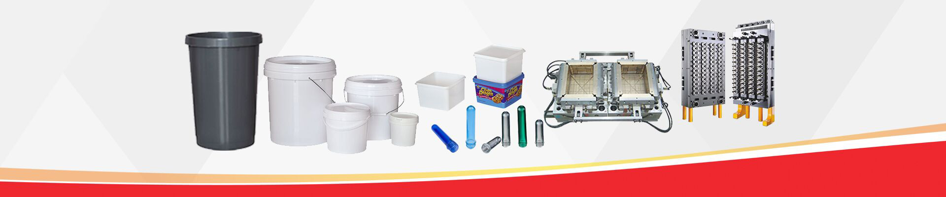
Feed system is the runner part for plastics to go into cavity from nozzle.It includes main runner,cold-slug well, sub-runner, and sprue.Molding components are the elements forming product's shape, like movable mold, stationary mold, cavity, core, molding rod, and vent.Typical plastic mould structure is as picture shows here.
1. Feed System
Feed system is also named as runner system. It's a group of feeding channels that lead plastic melt from injection machine to cavity. It mainly consists of main runner,sub-runner,gate and cold-slug well. It has the direct bearing on plastic product's forming quality and production efficiency.
A. Main Runner
It's a channel connecting injection machine nozzle with sub-runner or cavity. The top of main runner is concave in shape,easy for connecting with nozzle. Inlet diameter for main runner should be slightly larger than nozzle diameter (0.8mm) for avoiding spilling and preventing blocking caused by their inaccurate connecting. Inlet diameter depends on the dimension of product.Usually,it's 4-8mm. Main diameter should be expand inward an angle of 3° to 5° to help runner redundancy demould.
B.Cold-Slug Well
It's a hole at the end of main runner for gathering the cold slug left at nozzle's ends between two injection molding,thus protecting sub-runner or gate from blocking. If cold slug mixes into cavity, it will lead to internal stress in product. Cold-slug well's diameter is about 8-10mm,and depth is 6mm. For ease of demoulding, its bottom is usually supported by knockout pin. The top of knockout pin is better to be designed as tortuous hooked shape or set notch groove on it.Then the main runner redundancy will be pulled out smoothly while demoulding.
C.Sub-runner
It's channel connecting main runner with every cavity in subcavity mold.In order to make melt fill every cavity with uniform velocity, the arrangement of sub-runner on plastic mould should be symmetrical and equidistant distribution.The shape and size of sub-runner section have affects on melt's flowing, product's demoulding and the difficulty of mould manufacturing. At same feeding rate, the runner resistance for circular cross section is smallest. But cylindrical runner is not good for cooling of sub-runner redundancy, because its specific surface is small too. And this kind of sub-runner must be made on half mould. It takes a lot of work and easy for alignment. So sub-runner with trapezoid or semicircular section are often used and mded on the half mould with knockout pin. Runner surface must be polished to reduce flow resistance and offer high mould filling speed. Runner's dimension depends on plastic brands, product sizes and thickness. For most thermoplastic plastics, Sub-runner section width is no more than 8mm. The largest can be 10-12mm, and the smallest can be 2-3mm. Under the precondition of meeting the demand, minimize sectional area in case of increasing sub-runner redundancy and extending cooling time.
D. Gate
It's the channel connecting main runner (or sub-runner) with cavity. Channel sectional area can be same as main runner (or sub-runner), but usually it's smaller.So it's the part where the sectional area is smallest in runner system. Shape and dimensions of gate affect product's quality a lot.
The functions of Gate:
1) Control material flow speed.
2) Use premature condensation at this place to avoid flow backward while injecting.
3) Use strong shear on melt flowing through to raise the temperature, which will reduce apparent viscosity and enhance liquidity.
4) Easy for product to separate with runner system. The design for shape, size and position of gate depends on plastics properties, product dimension,size and structure. Usually, gate section shape is rectangular or circular. Sectional area should be small and its length should short.This is not only based on the above roles,but also that it's easy for small gate to be larger and hard for large gate to be smaller. The position of gate often is at the thickest place of product without any influences on its appearance. The design for gate size should take plastic melt's properties into consideration.Cavity is the space for forming plastic product in mould. And the elements used for making cavity module are called by a joint name--molding component. Every molding component often has a specified name. The molding components constituting product's external shape are named as concave die (also known as female mould) .Those constituting product's internal shape (like hole,groove,etc.) are named as core or terrace die (also known as male mould).For designing molding components, the cavity overall structure should be decided firstly according to plastic properties, product geometric shape,dimensional tolerance and operating requirement.Secondly,choose parting line, position of gate and vent hold and demoulding method based on the determined structure. Finally,according to product dimension, design the components and their compound mode.There is high pressure while plastic melt enters cavity, so molding components need reasonable material selection and verification for strength and stiffness. In order to make plastic product's appearance clean and aesthetic and easy to demould, for all surfaces touching plastic, their roughness should be Ra>0.32um and must be corrosion resisting. Molding components usually need heat treatment to enhance their hardness. And they need be made of corrosion resistant steel.
2.Temperature Adjusting System
For meeting the requirement of injection molding technology on mold temperature, it needs temperature adjusting system to adjust mold temperature.For injection mould with thermoplastic plastics, mainly cooling system is designed for cooling mold. Common method for mold cooling is setting water cooling channel in mould and using circulating cooling water to take the heat of mould out. For mould heating, we can not only use hot water or steam in cooling water channel, but also install heating elements on mould mould interior and periphery.
3.Molding Component
Molding components consist of core and cavity. Core forms product's internal surface,and cavity forms product's external surface. After closing mould, core and cavity compose the mould cavity. As technical and manufacturing requirements, sometimes core and cavity are combinations of several blocks, and sometimes are a whole part with inserts only for places that easy to damage and hard to process.
Vent
It's a groove-shape gas outlet made on mould, for expeling original airs and those brought in by melt. When melt enters cavity, the original airs in cavity and airs brought in by melt must be expelled from mould via vent at the end of melt flow.Otherwise,product will have porosity,plate mark,and short shot. What's worse, air stockpile in compression may cause high temperature and make product get burnt. In general, vent hole can be made at the end of melt flow in cavity,and also could be on mould parting surface.The latter is making shallow slot with depth of 0.03-0.2mm and width of 1.5-6mm on cavity. During injecting, there will not be many melt oozing from vent hold, because melt cooled and solidified here will block the channel.The position of vent hold should never face to operators,in case that melt erupt accidently and hurt them.Besides, we also can use the fit clearance between ejector rob and ejector hold and that between ejector block and knockout plate for venting.
4.Structural Component
It refers to the elements composing mould structure, including components for guiding,demoulding,core-pulling and parting, like front and back clamp plate,front and back fixing plate,bearing plate,bearing pillar,Guide Pillar,striper plate,ejector rod and return pin.
a. Guiding Elements
To make sure that core and cavity can accurately assemble when closing mould, there must be guiding elements on mould. Injection mould usually adopts four groups of guide pillars and guide sleeves. Sometimes consistent internal and external conical surface will be set additionally on core and cavity for auxiliary positioning.
b. Extrusion Device
During opening mould, it needs extrusion device to push out or pull out plastic product and condensed material in runner. Retaining plate and stripper plate are used for clamping puncher. Usually there are return pins fixed in punchers. Return pin is for resetting stripper plate while core and cavity close.
c. Side action mechanism
Some plastic products have undercuts or side holes. Before being pushed out, they need side parting to pull out side core first. Then they will be able to demould successfully. At this time, side action mechanism need be made on mould.
d. Standard Mould Base
For reducing heavy work for mould design and manufacturing, most injection moulds use standard mould base.

